
UN series
Optical Data Transmission System
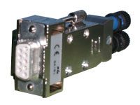
As a system of optical links this product line enables the user to establish optical connections between various different computers via RS232 (V24). This version consist of an opto-electronic transceiver within a standard plug.
Within this product line, a powerful and easy to use plug & play system can be installed.
Two different connectors are available: one for plastic fibres and one for glass fibres. When using plastic fibre, only a sharp knife is needed for installation. Units arranged for glass fibres are equipped with standard ST-series fibre optic connectors. The user can attach the fibre without opening the plug.
The product line UN-Series allows a low cost, robust and reliable link.
No external power supply is required. The power for the transmit and receive circuitry is drawn from the port of the connected equipment.
- Optical connection between two devices RS232C
- Interference free data transfer using optical fibre
- The housing consist of a metallized plastic hood with screw-locking
- Serial, asynchronous and full duplex data transfer
- Full galvanic isolation between connected devices
- No external power supply required
- Not for optical data transfer to and from externally powered modules
- Xon / Xoff protocol
- Data rate up to 40 kbit/s
- 9-pole D-Sub socket
Technical Data
- Max. data transfer rate: max. 40 kbit/s
- Max. distance:
Type UN1373B max. 60 m with cable 2 x 1000µm PMMA-fase
Type UN6373B max. 1000 m with glass fibre cable / connection pin - Wavelength:
Type UN1373B 660 nm
Type UN6373B 850 nm - Connector: D-Sub 9-pole socket
- Compatible: IBM compatible
- Operating temperature: 0°C to +65°C
- Storage temperature: -20°C to +85°C
- Dimensions (L x W x H): 71 x 32 x 21 mm3
- Weight: 45 g
Always use two modules of these group!
Because of different sensitivities and power products they will not work in combination with products belonging to other groups.
Connector layout
| Pin | Symbol | Signal name | Comments |
| 1 | connected with Pin 4 and Pin 6 | ||
| 2 | RxD | Receive Data | |
| 3 | TxD | Transmit Data | |
| 4 | connected with Pin 1 and Pin 6 | ||
| 5 | GND | Signal Ground | |
| 6 | connected with Pin 1 and Pin 4 | ||
| 7 | connected with Pin 8 | ||
| 8 | connected with Pin 7 |